|
I've now replaced the new sheaves that came with the new
masthead with 1/4" sheaves, the wire halyards with 1/4" StaSet-X
line. I've added a spinnaker crane this year while I'm at it.
The trick to switching out sheaves is to position the mast so the
spreaders are pointing up and down; then the clevis pins slide in and
out without losing the sheaves and separator plate. (Apr.
10, 2004)
|
|
Another view from the top of the mast.
I've still got to remount the Windex and the VHF antenna. |
|
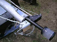
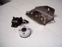
This is the old-style aluminum
spreader bracket, which I attempted to replace today with the stainless
steel upgrade. I removed the old ones, but ran into a roadblock with the
instructions for installing the new ones -- there were no
instructions --
and there was a "mast compression tube" included
in the kit that apparently needs to go up inside the mast for a
bolt to run through. Thanks to friends in the C22 discussion group,
I've been advised of a few tricks that will accomplish it, maybe
tomorrow ... if I can find an old hose or 14' of PVC pipe. (Apr.
10, 2004) |
From Catalina Direct's
Ship's Store page |
Stainless Steel Spreader Brackets
(Oval Mast) Upgrade Kit --
Catalina Direct Product #: D109 |
|
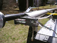
The next day, using a length of garden
hose, I drilled a 1/2" hole through the end and inserted the
compression tube through it, slit the hose on both sides from its end to
the hole/compression tube, then tightly wrapped the end with a small
rubber band. I measured and marked the hose so I'd know when the tube
reached the 5/16" holes I'd drilled through the mast. Inserting the
hose/tube into the base, maneuvering it up around the mast wiring
harness and
antenna cable that exit on the port side base of the mast, it easily pushed
up to the mark on the hose. With a helper at the hose end, using an awl I
lined up the holes and compression tube and inserted a bolt. (Apr. 11,
2004) |
|
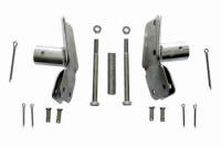
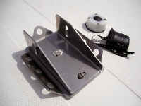
Both 4" bolts from the Catalina Direct kit I'd
purchased were about 5/8" too long and
couldn't be tightened to the mast (wonderful)! On Day 3 of what
should have been a minor project, I bought two 3 1/2"
stainless steel bolts which fit perfectly. After struggling with a frustrating Catalina Direct kit, despite no
instructions and bolts that were too long, the new-style spreader
brackets are
installed. I removed the garden hose with one firm pull, attached the
spreaders, and can finally move on -- three days later --
having finally completed what should have been about a two-hour job! (Apr.
12, 2004) |
Detailed instruction page on how
to install the new-style spreader brackets
 in PDF format
requires free
Adobe PDF Reader
|
|
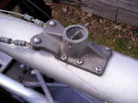
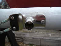
The original mast step plate. (Note
the AquaSignal deck connector for the mast wiring, and the Blue Sea
cable clam for the VHF radio antenna coax cable up to the masthead, both
of which I installed last season as part of my rewiring project.) |
|
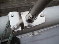
A view of the old-style mast step
plate from the starboard side. |
|
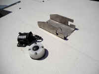
The new mast step plate and halyard
plate, from the port side. (Apr. 17,
2004) |
|
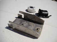
The new mast step and halyard plates,
from the starboard side. |
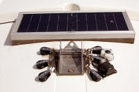 |
The mast step, turning blocks, and deck connectors (with the
solar panel behind) --
April, 2007. |
| NEXT
|
| It's never-ending ...
but the best times are again growing even closer yet! |