|
Back on Oct.
27th I observed: "One of my upcoming winter projects
this year will be reconditioning Chip Ahoy's rudder: there's too
much "slop" in it, which means I'll have to disassemble the
blade from its housing and shave the housing down a bit. I'd hoped
I eliminated that "slop" last year, but failed."
Yesterday it was time to take on this
project. (Jan. 30, 2005) |

|
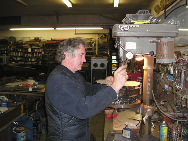
I brought the rudder up to longtime
friend Brad Barrows' garage. Brad builds hot-rods fulltime and is the
best self-taught mechanical engineer I've ever known since I first met
him. (He and I restored
and lived aboard the Even Song and
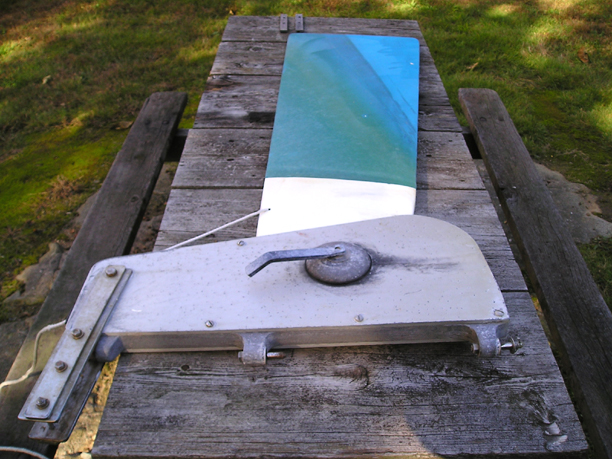
Idle Hours II some two decades ago.) It may not look it here, but the
MarineTex gouge repair I did last year held up fine. Still, there was
too much port-starboard slop between the rudder and its aluminum
housing. |

|
Having decided to first try building
up the rudder blade before disassembling the housing and weakening it by
reducing the thickness of its solid spacer, Brad came up with the idea
of cutting a piece of thin (about 1/8") fiberglass he had and
forming a spacer on each side between the rudder and its housing. |

|
Cutting two pieces of it to size and
shape then drilling out a hole for the pivot bolt, we put the rudder
back together. There was still a bit too much slop. |

|
Brad analyzed the result and concluded
that we needed to increase the thickness of our homemade spacers, then it
would work. What a tremendous workshop/garage he's built.
He's a
professional hot-rod builder -- and I mean builder from virtually
scratch: he takes piles of 75-year old antiques and more current cars and parts,
fuses them together, and
creates something entirely brand new that is literally a work of art,
over and over again! He built
his garage from scratch to accommodate his lifestyle and has populated
it with tools and
equipment over decades. |

|
It was an awesome experience working on Chip
Ahoy at a location where every tool and piece of equipment you could
only dream of was available: just reach for it or ask where it is! Brad decided to use two pieces of
slightly thicker aluminum (about 3/16") that he had in his stock of
materials. While he was cutting and preparing it, I used his table
sander to to cut down the three "teeth" on both of the
circular rudder clamps to accommodate the the additional rudder
thickness we were creating. |

|
Once the new aluminum plates were ready to
install, Brad permanently glued them to the rudder blade, peened over the
curved edges, and finally we reassembled the rudder and tightened down
the center clamp. We had acquired perfect spacing between the blade and
housing: with the center clamp loosened, enough for the rudder to
move up and down freely; but tight with the clamp tightened down. The
slop was eliminated! |

|
The finished rudder assembly. |

|
All the "slop" has been
eliminated. In fact, I later had to file and sand down the
aluminum plates in spots to eliminate some binding against the housing
when raising and lowering the rudder. Next, I have to figure a way to raise
the rudder blade fully out of the water. Brad suggested
extending the tiller bracket further outboard: we agree that the
designer gave no consideration to lift leverage.
Related project:
Increasing Rudder Lift Leverage
|
| Moving on
with Season 2005 improvements |
|
It's never-ending ...
but winter has arrived and Sailing Season '05 is coming! |