|
When I first uncovered and inspected
Chip Ahoy (then still named "Take Five"), I was astonished to
find it had no bilge pump. Every boat I've ever owned or sailed on has had a
bilge pump! I set about installing one. The first step was cutting a
1-1/8" hole in the hull and installing a thru-hull fitting
(sealing it on both ends with 3M 4200). I put it as high above the
waterline as possible, with a plan to bring it even higher. |

|
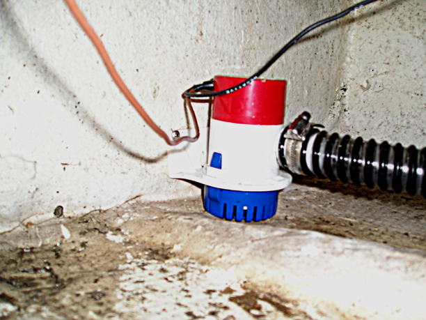
Next, I mounted a Rule 1100 (GPH)
pump, fastening it to the aft bilge bulkhead behind the "volcano,"
beneath the cockpit liner, and attached 10' of 1-1/8" hose. |

May 2009 |
Note: In the May 2009 issue of MainBrace (the bimonthly
publication of the
Catalina 22
National Sailing Association for which I am its
technical editor), my article was titled "The Bilge Pump Debate." I
took some new photos of the bilge pump setup for it, which I've added here
and below. |
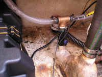 |
Photo taken in 2004, after
installing a second battery and
replacing the scupper drain hoses and hull fitting. |
|
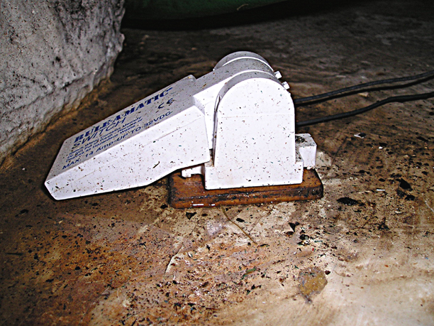
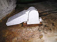
I epoxied a small piece of plywood to
the interior hull immediately behind and as close to the cabin liner as
possible (the lowest point of the aft bilge), then fastened a Rule float
switch to it. |

May 2009 |
Note the small piece of closed cell styrofoam I
subsequently glued to the bottom of the lever, to
compensate for the piece of plywood raising the float switch. |
|
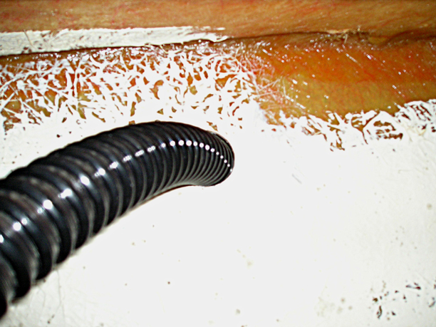
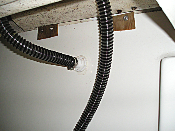
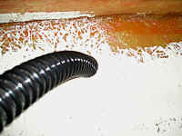
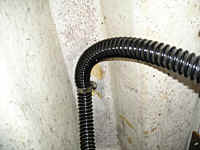
I cut a 1-1/8" hole in the port
side bilge bulkhead liner beneath the aft settee seatback and
ran the hose around and up through it. |
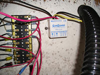 |
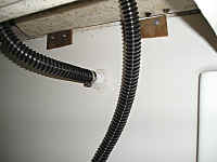
Another view, the photo taken after installing a small buss
and a solar panel controller. |
|
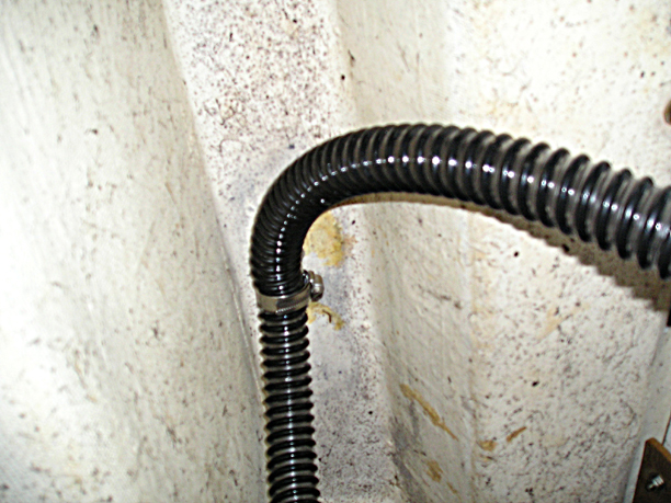
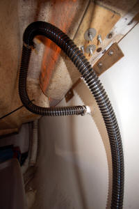
From there, I ran the hose up to the
interior top of the
coaming and attached it to a fair lead/eye-strap, with the eye-strap's screws entering from the outside
topside (see photo below), and ran a hose clamp through the eye-strap lead and secured the
hose. |
 |
A view of the screws with finishing
washers holding the eye-strap below
deck. |
May 2009 |
What a difference a
wide-angle lens
makes in capturing a larger area! I used the Sigma EX 10-20mm on my
Nikon D50 DSLR for the MainBrace (May 2009) photos. The other
photos on this page were taken with an Olympus pocket camera that's
always onboard, usually within reach. |
|
Then I dropped the hose down to the
thru-hull fitting and fastened it. This and the previous steps
prevents backfill, as it requires a higher outside water level than the thru-hull fitting:
even on a starboard tack with the portside rail awash the ocean doesn't infiltrate into the bilge
until and unless the coaming is under water and the cockpit is filled. (I used a
heat gun to soften the hose end enough to squeeze it over the fitting, then
hose-clamped it.) Through the new hatch
access door I later had built, I'm able to easily access it if
necessary from behind the aft settee seat cushion. |
|
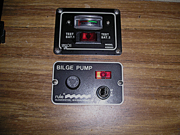
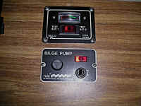
Finally, I added a Rule
manual-automatic bilge pump switch to the panel behind the
companionway step and wired everything up.
Wiring Diagram
JPG Diagram
| PDF
Diagram |
|
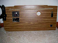
A closer view of the panel switch. |
May 2009 |
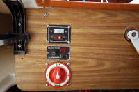
The voltmeter switch is at the top, the bilge pump switch
in the middle. Beneath it is the 4-way selector switch for controlling
the two batteries, which I added in 2004. |
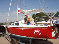 |
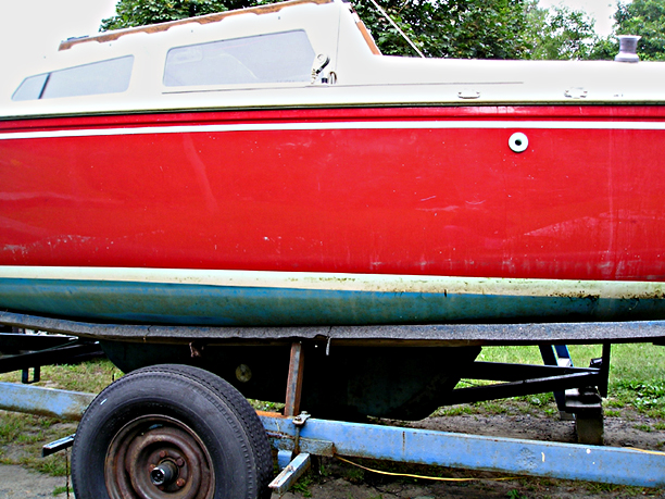
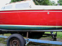
Chip Ahoy being readied for imminent launch in 2006. The bilge
pump discharge fitting is just beneath the cove stripe below me in the
photo. |
| It's never-ending ...
but the best times are again growing even closer yet! |